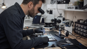
A thermal camera helps us find where a powered motherboard is producing heat. That can narrow a search for a short circuit, but a bright spot is a lead to investigate, not proof that the component underneath must be replaced.

What the camera can tell us
When a board draws abnormal current, one area may heat up before the rest. Watching that change can help locate a fault that is difficult to spot visually. It is particularly useful when several components share the same power rail and electrical measurements have already narrowed the search.
The hot component may be faulty, or it may be carrying current to a fault elsewhere. Heat also spreads through the board. We check the circuit electrically before deciding what to remove.
What it cannot see
A thermal camera measures infrared radiation from visible surfaces. It cannot see through a metal shield or reveal every part on a stacked phone motherboard. A shield can warm as heat reaches it from below, but that does not identify the component responsible. FLIR explains these material limitations.
A cold processor is not proof of a dead processor either. The board may not have reached the stage where that circuit is enabled. Firmware, control signals and power sequencing can require other tests.

Why there is no universal temperature table
The same reading can mean different things on different boards. The model, workload, supply voltage, current limit and room temperature matter. Shiny metal surfaces can also give misleading readings because they emit and reflect infrared radiation differently from surrounding materials.
We look at the pattern and how it develops under controlled conditions, then compare it with the circuit’s expected behaviour. A temperature quoted without those conditions is not a useful pass or fail threshold.
How it fits into a repair
- Inspect the board and establish the electrical fault. A liquid-damaged device needs inspection before further power is applied.
- Use controlled power and thermal observation where appropriate to narrow the affected area.
- Confirm the suspected fault with electrical measurements and inspection.
- After repair, check the affected circuit and test the device’s original symptom again.
This is bench work, not a home test: applying the wrong voltage or current can damage a recoverable board. Thermal imaging is less useful for faults that do not produce a distinctive heat pattern, including many signal and software problems.

Does a board fault mean replacing the board?
Sometimes a localised component fault can be repaired while keeping the original board. Sometimes the damage is more extensive, or a reliable repair is not economical. Thermal imaging helps inform that decision; it cannot guarantee either outcome.
If your device has stopped working, book an assessment and describe the symptom and any spill or previous repair. We can then assess whether component-level repair is a sensible option. If the files are the priority, tell us before work begins.